OptEM Connector - Software for Modeling High-Speed High-Performance Connectors
OptEM Connector
OptEM Connector
OptEM Connector is a CAE software tool used for the modeling and analysis of high-speed connectors and related interconnect media.

Product Description
OptEM Connector is used by engineers developing connectors for systems with high-speed high-performance data transmission. Critical concerns for connector development engineers include lossy and frequency-dependent characteristics of the connector, and impedance control. To minimize reflections designers must compensate for sections with lower impedance while keeping in mind the requirements for signal speed and frequency range.
Using OptEM Connector an engineer can model cross sections and observe R, L, C, G, and characteristic impedance (Zo) results, as well as create transmission line models for analyses like TDR, ground bounce and near/far end crosstalk simulation. OptEM Connector also assists with the detailed analysis of conductor and shield losses resulting from skin effect and proximity effect.
System designers require connector and cable transmission line characterization for high-speed simulation to properly account for time delays, impedance mismatch, and additional crosstalk effects caused by connectors and cables within their system.
DXF Input & Geometry Extraction
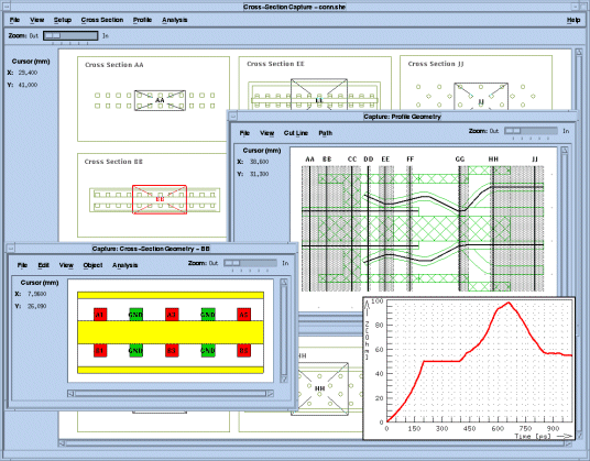
OptEM Connector reads DXF CAD files from which multiple cross-section regions are captured and extracted in a matter of seconds. The material properties and conductors within each cross section are assigned using object definitions. An object definition includes the type of material, on-screen color, naming rule, plating, and conductor type (signal or ground). Modeling efficiency and flexibility is enhanced through editing features.
Profile Modeling
Often the profile of a connector is also drawn on the same sheet as the cross sections. A complete model of a connector is created by assigning each extracted cross section to a position within the profile. OptEM Connector then concatenates each cross section within the profile and is able to automatically model the nonuniform geometry located between cross sections. The SPICE model generated by the software is an accurate representation ready for circuit simulation and system modeling.
System Modeling & Analysis
OptEM Connector provides a schematic capture facility which allows connectors, cables and other interconnect media to be assembled into a system model. A circuit analysis of the entire system is performed and results are calculated for TDR, characteristic impedance, S-parameters and crosstalk.

Features & Benefits
Features
- DXF interface
- loads entire connector drawing
- uses profile to create complete connector model
- automatic pin naming
- supports conductor plating
- object definitions for faster modeling capability
- performs frequency-dependent electromagnetic analysis and generates R, L, C, G and SPICE models
- calculates time domain reflectometry (TDR), characteristic impedance values, S-parameters, and crosstalk effects
- batch analysis
Benefits
- uses standard manufacturing files
- extracts cross sections quickly and efficiently
- allows simulation of connectors within a system environment
- concurrent modeling and analysis
- inclusion of losses in the EM field analysis provides accurate L, R, C, G reports and transmission line models
- generates complex multi-port S-parameters
- transient simulation of reflections and crosstalk
